+251 99 380 2995 | +251 97 022 2227 | [email protected]

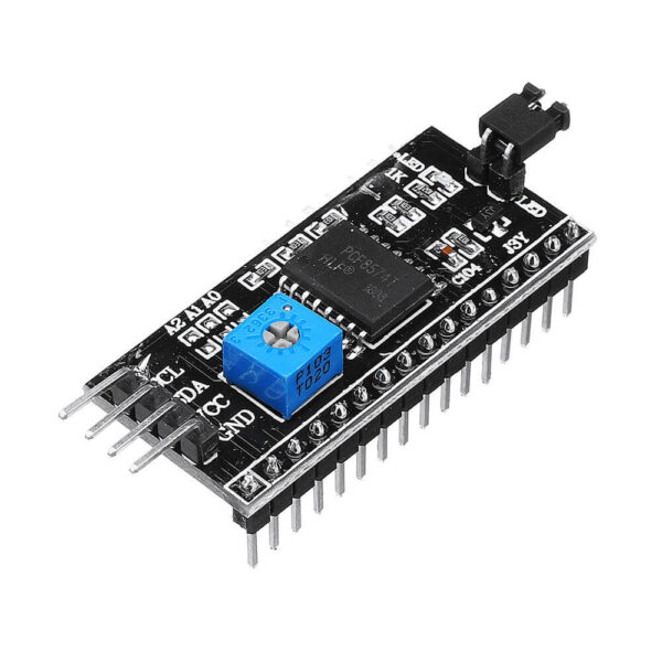
I2C Module
Br 500.00
- Provides I2C to parallel data conversion
- Backlight enable jumper
- Contrast control potentiometer
- 0x27 I2C default address. Solder jumper selectable from 0x20 – 0x27
- 100kHz I2C clock speed
- 5V operation typical, but also operates at 3.3V.
- This LCD I2C interface adapter can be added to a 16 x 2 or 20 x 4 character LCD display with a standard parallel interface to make it I2C compatible. It can also be repurposed for other I2C to parallel tasks.
- The board has a PCF8574 I2C chip that converts the I2C data from an MCU into 4-bit parallel data and control bits required by the LCD display.
- By default, the industry standard HD44780 compatible 16 x 2 and 20 x 4 character LCD displays require 4 or 8 parallel data lines to drive them along with a couple of pins for chip select and chip enable. This consumes a lot of pins on the MCU. This adapter board reduces the data pin requirements to only 2 pins which can also be shared with other I2C devices.
- The backlight can be controlled ON/OFF, but the intensity is not directly controllable though the I2C interface. Some modules have a jumper on the board that supplies Vcc power to the backlight. That jumper can be removed and a voltage applied to the header pin nearest the ‘LED’ markings on the board to provide power to the backlight separately.
- The PCF8574 is a generic I2C to 8-bit I/O device and the module can be repurposed for other uses besides driving LCD modules. Max I2C clock frequency is 100kHz which makes it most suited to lower speed applications.


