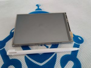
Alphanumeric LCD display module to display letters(alphabets), numbers, and symbols.
In this module there are 2 main types of register first one is data register and the second one is command register. The RS pinout is used for the change the register.
If we set zero then the register is command and at one data register will work.
Command Register
The main function of this register is to save instructions shown on display.
That help to a clearing of data changes the location of the cursor and display control.
Data Register
This register saves the date to display on the liquid crystal screen. When we send data to liquid crystal display it moves to the data register, processing of that data will initiate.
If we set the value of register at one then the data register will start operation.
16×4 LCD Pinout Configuration
Pin 1(Vss (Ground)) Ground pin connected to system ground
Pin2(Vdd (+5 Volt)) Powers the LCD with +5V (4.7V – 5.3V)
Pin 3(VE (Contrast V)) Decides the contrast level of display. Grounded to get maximum contrast.
Pin 4(Register Select) Connected to Microcontroller to shift between command/data register
Pin 5(Read/Write)Used to read or write data. Normally grounded to write data to LCD
Pin 6(Enable) Connected to Microcontroller Pin and toggled between 1 and 0 for data acknowledgement
Pin 6(Enable) Connected to Microcontroller Pin and toggled between 1 and 0 for data acknowledgement
Pin 7-14 (Data Pin 0-7) Data pins 0 to 7 forms a 8-bit data line. They can be connected to Microcontroller to send 8-bit data. These LCD’s can also operate on 4-bit mode in such case Data pin 4,5,6 and 7 will be left free.
Pin 15(LED Positive) Backlight LED pin positive terminal
Pin 16(LED Negative) Backlight LED pin negative terminal